

Polarity
Polarity is the direction of current flow in a circuit from the two poles, positive and negative. You require two points of differential charge for any electron movement to take place.
In an AC circuit, each pole alternates between positive and negative 60 times per second. You can see from the image of the AC sine wave, that the change in polarity of AC does not happen instantly, although close to and 60 times per second (Hertz).
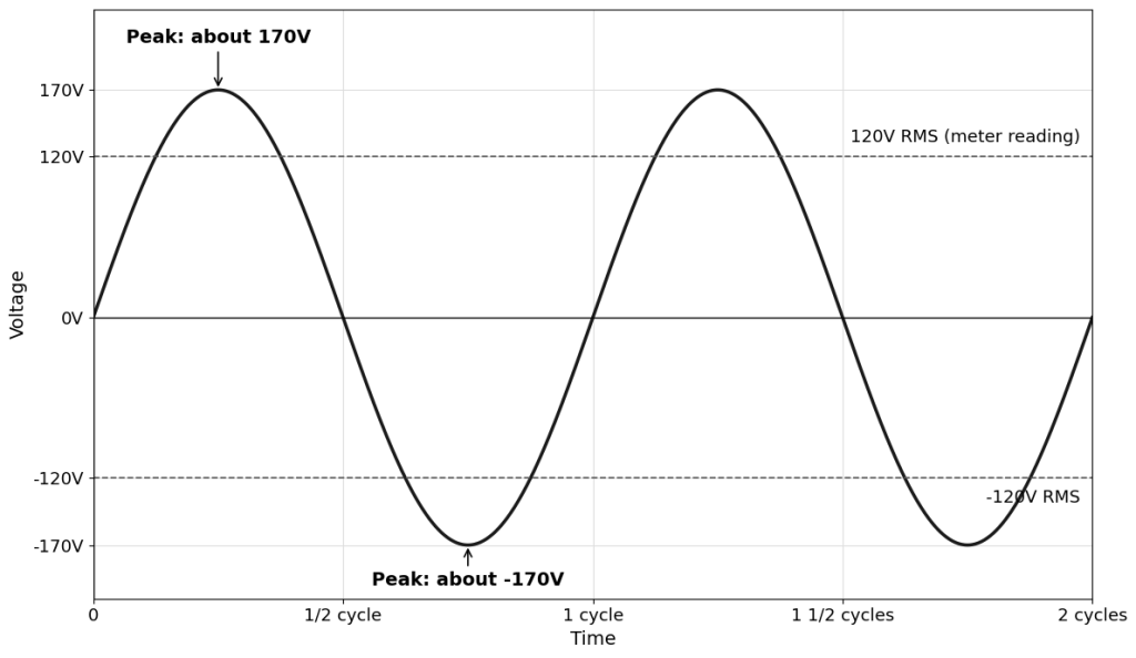
(Top positive side of the sine wave) Voltage increases from 0V to its max “peak” voltage, which is about 170V in the above example, while a meter reads 120V RMS. At that point, the voltage then begins to decrease back to 0V.
(Bottom negative side of the sine wave) The voltage then reverses polarity and drops below 0V, again heading for the peak voltage but the negative polarity.
In a DC circuit, it’s between the negative and positive with current flowing from negative to positive.
What this means on a service call
Polarity decides which lead is positive and which lead is negative at the moment you test. Get the leads backwards and your reading, your wiring, and your diagnosis can all point the wrong way.
In a DC circuit, polarity stays put. One side stays positive and the other side stays negative while the circuit is powered. Current flows from negative to positive in the original lesson, and the load, the control, and the meter all expect the same two sides in the same places. Swap the two wires on a DC control or a DC powered part and the part may not work, even though voltage is present.
In an AC circuit, polarity changes. Each pole alternates between positive and negative, as the original lesson states. That does not mean the wires are interchangeable in every case. On HVAC equipment, the hot side, the neutral or common side, and the ground side still have assigned places on the transformer, the control board, and the thermostat connections. Put a wire on the wrong terminal and a control may not call, a safety may not prove, or a meter reading may not make sense.
On a service call, start by naming the two points you are testing. Say which lead is on which terminal, and say whether you expect that point to be positive, negative, hot, or common at that moment. If the names do not match the wiring diagram, stop and sort out the wiring before you replace a part.
Numbers and measurements you will see
Use the numbers that belong to the circuit in front of you. A control circuit is commonly 24V. A line circuit is commonly 120V. AC in the original lesson alternates 60 times per second, which is 60 Hertz. Your meter will show those values in different ways depending on the leads.
- 24V on a control circuit, measured from R to C on a transformer or a control board. A reading near 24V tells you the transformer secondary is powered. A reading of 0V tells you it is not, or that you are on the wrong two points.
- 120V on a line circuit, measured at the disconnect or at the line side of a control. The meter displays 120V when the leads are on the two points that carry line voltage.
- 0V at the crossing point on an AC sine wave. Voltage passes through 0V as it changes from positive to negative and back again. A steady 0V reading on a powered circuit usually means the meter is on two points at the same potential, or the circuit is dead.
- A negative sign on a DC reading when the leads are reversed. If you expect positive 24V and the meter shows negative 24V, the leads are on opposite points from the way you expected. Swap the leads and recheck before you decide the circuit is wrong.
- 60 Hertz on an AC circuit. A meter with a Hertz setting should show 60 Hertz on a standard AC supply. A reading far from 60 Hertz, or no Hertz reading at all, tells you to recheck the meter setting and the test points.
- Positive on one lead and negative on the other in a DC circuit. The two readings should be opposite in sign and equal in size when you swap the leads. If they are not, one test point is not what you think it is.
A common mistake
Treating AC wires as if polarity never matters is the common mistake. A technician swaps two wires, the equipment still gets power, and the technician assumes the swap is fine.
Power at the equipment does not prove the control wiring is right. A thermostat, a control board, and a safety control each expect specific terminals to be hot, common, or switched. A swapped pair can leave a control with no clear call, or with a call that never clears. Put each wire back on the terminal shown on the wiring diagram, and test from the diagram, not from memory.
A second mistake is reading a negative DC voltage and calling the circuit dead. A negative reading is still a reading. It tells you voltage is present and the leads are reversed from the polarity you expected. Swap the leads, note the sign, and use the result. Do not ignore the minus sign.
Check it in the field
Caution: live and powered work can hurt you. Treat a circuit as live until you prove it is dead with your meter. Keep your hands clear of bare conductors and terminals. If you are not sure a test is safe, stop, turn the power off, and get help. Do not bypass a switch or a safety control to force a load to run.
- Identify the two test points from the wiring diagram before you touch the meter. Name each point and note whether it should be hot, common, positive, or negative.
- Set the meter for the circuit you are testing, AC voltage for an AC circuit and DC voltage for a DC circuit. Check the meter on a known source first.
- Place the red lead on the point you expect to be positive or hot, and the black lead on the point you expect to be negative or common. Read the number and the sign.
- Swap the leads and read again. On DC, the size should stay the same and the sign should reverse. On AC, the size should stay about the same. If the readings do not match that pattern, recheck the test points and the meter setting.
- On a 24V control circuit, measure R to C. Expect about 24V. Then measure from R to the terminal in question. A missing or wrong reading points to the wiring or the control, not to the meter.
- Turn the power off before you move a wire. Put each wire on the terminal shown on the diagram, tighten the connection, restore power, and retest with the leads in the same places you used first.


