Author: Jesse

The Basic Refrigeration Cycle: How Heat Actually Moves (And What Each Part Does)

The Basic Refrigeration Cycle: How Heat Actually Moves (And What Each Part Does)

Air conditioners and walk-in coolers do not create cold. They remove heat from an area where you do not want it and dump it somewhere where it does not matter.

To move that heat, the system circulates refrigerant through a closed loop of copper tubing. By changing the pressure of the refrigerant, the system forces it to boil at cold temperatures to absorb heat indoors, and condense at hot temperatures to dump heat outdoors.

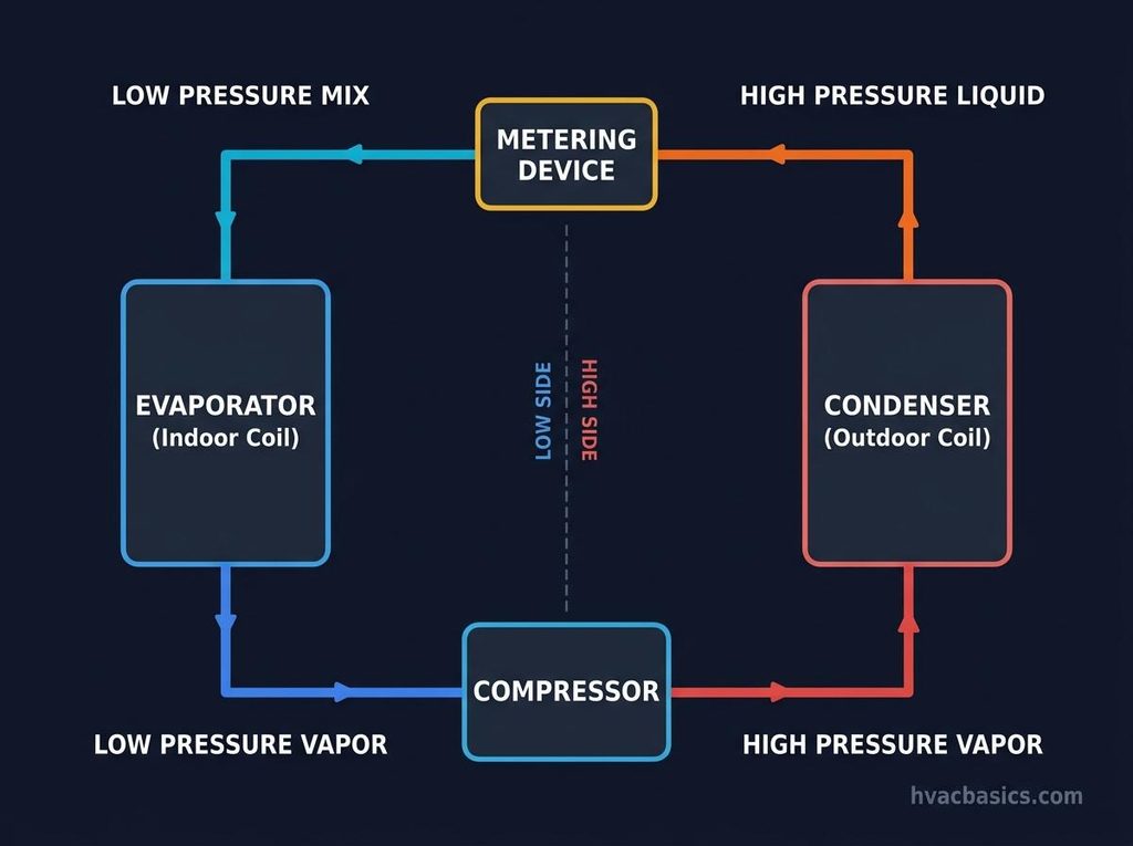
Every standard vapor compression system relies on four primary components to make this happen:

  1. Compressor
  2. Condenser
  3. Metering Device
  4. Evaporator

The Four Primary Components

1. The Compressor (The Vapor Pump)

The compressor sits between the low side and the high side of the system. Its job is simple: draw in low-pressure, low-temperature vapor from the evaporator and squeeze it into a high-pressure, high-temperature superheated vapor.

Compressors are vapor pumps. They are designed to compress gas, not liquid. Pumping liquid refrigerant or oil into the cylinders or scrolls will break valves, bend connecting rods, or blow out scrolls.

2. The Condenser (Heat Rejection)

The hot, high-pressure vapor leaves the compressor through the discharge line and enters the outdoor condenser coil. Here, outdoor air (or water in water-cooled systems) blows across the coil fins.

Because the refrigerant is hotter than the outdoor air, heat transfers out of the refrigerant into the ambient air. As it cools, three distinct stages occur in the condenser:

  • De-superheating: The hot discharge gas cools down to its condensing saturation temperature.
  • Condensing: The refrigerant changes state from vapor to liquid at a constant saturation temperature.
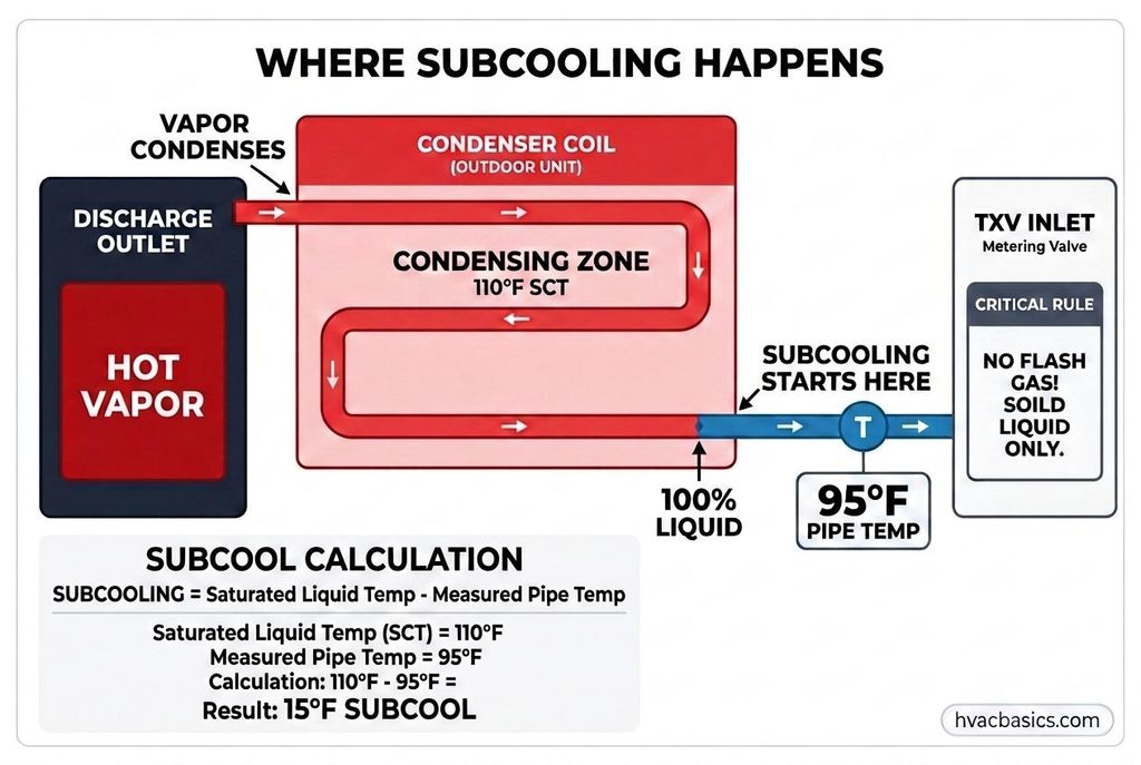
  • Subcooling: Once the refrigerant is 100% liquid, it continues to cool a few degrees further below its condensing temperature before exiting through the liquid line.

3. The Metering Device (The Pressure Dropper)

The metering device (a Thermal Expansion Valve [TXV], electronic expansion valve, or fixed orifice) acts as a dividing point between the high side and the low side. It restricts the flow of liquid refrigerant feeding into the evaporator coil.

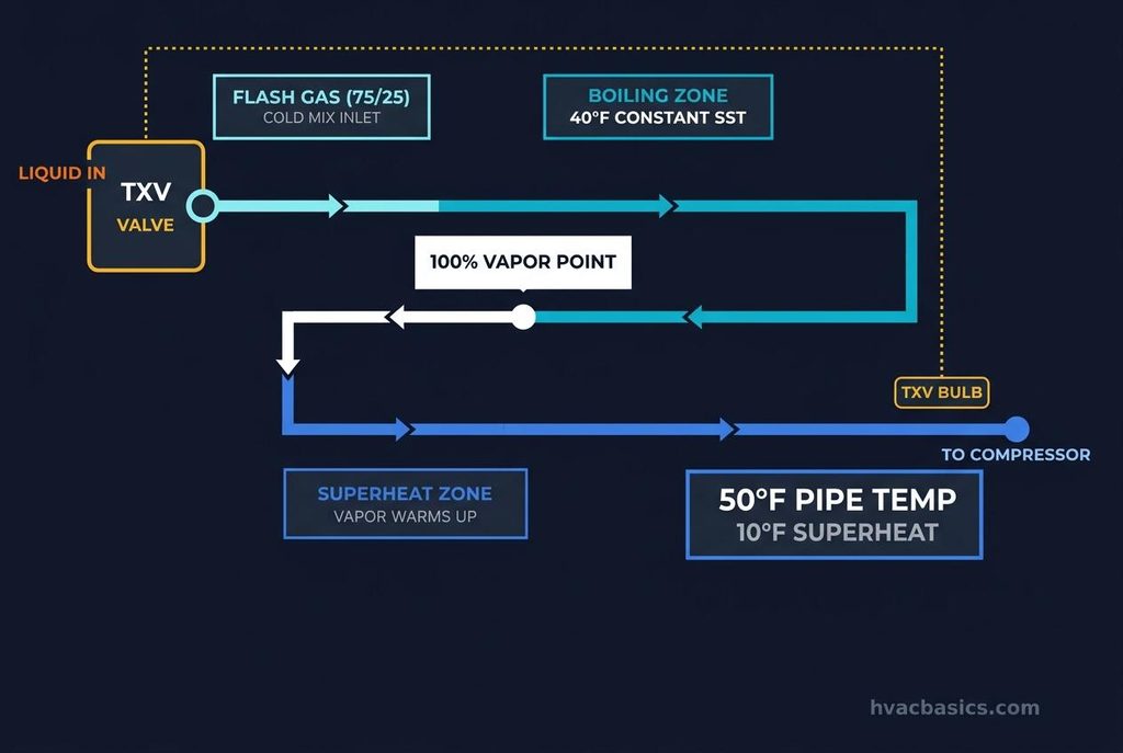
When high-pressure liquid is forced through this small opening into the low-pressure side, the pressure drops instantly. That sudden drop causes roughly 20% to 25% of the liquid to immediately vaporize. This is known as “flash gas.” The flash gas instantly chills the remaining liquid down to the evaporator saturation temperature (typically around 40°F for standard air conditioning).

4. The Evaporator (Heat Absorption)

The cold mix of liquid and vapor enters the evaporator coil located inside the conditioned space or air handler. Indoor air blows across the coil fins.

Because the room air is warmer than the 40°F coil, heat transfers from the air into the refrigerant. The liquid refrigerant absorbs this heat and boils into a vapor. By the time it reaches the end of the coil, all the liquid has boiled away into 100% vapor, and the vapor warms up slightly (superheat) before returning to the compressor.
Field Measurements: Superheat and Subcooling

Checking pressures alone does not tell you how a system is running. You need line temperatures and saturation temperatures to calculate superheat and subcooling.

Superheat (Evaporator & Compressor Protection)

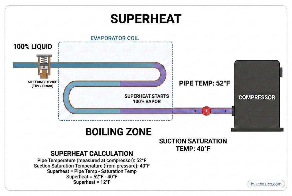
Superheat is the sensible heat added to refrigerant vapor after it has completely boiled off in the evaporator coil.

Superheat = Suction Line Temperature - Saturated Suction Temperature (SST)
  • Why it matters: Superheat confirms that no raw liquid refrigerant is leaving the evaporator coil to enter the compressor.
  • Typical target: 8°F to 12°F on a TXV system at the evaporator outlet (or 10°F to 15°F at the compressor inlet).
  • Too low (0°F to 4°F): The coil is flooding. Liquid refrigerant can wash out compressor oil and slug the compressor.
  • Too high (above 20°F): The evaporator is starved of refrigerant. The system loses cooling capacity and the compressor motor runs hot due to lack of cooling vapor.
Subcooling (Condenser & Liquid Line Quality)

Subcooling is the heat removed from liquid refrigerant after it has completely condensed inside the condenser coil.

Subcooling = Saturated Condensing Temperature (SCT) - Liquid Line Temperature
  • Why it matters: Subcooling guarantees that a solid, bubble-free column of liquid reaches the metering device without premature flashing in the liquid line.
  • Typical target: 10°F to 12°F (always verify against the manufacturer data tag).
  • Too low (below 5°F): Undercharge or flashing liquid line, causing the metering device to hunt or starve the coil.
  • Too high (above 18°F): Overcharge or non-condensables backing liquid up into the condenser coil, driving head pressure up.

Practical Troubleshooting Tips from the Field

  1. Check airflow before touching your gauges. A dirty pleated filter, crushed return duct, or failing blower motor drops coil load. This causes low suction pressure and low superheat, often leading to coil freeze-ups. Never add refrigerant until airflow is verified.
  2. Feel the filter drier. A restricted liquid line filter drier acts like an unintended secondary metering device. If you measure a temperature drop across the drier (more than 1°F to 2°F), replace the drier.
  3. Dirty condenser coils wreck efficiency. If the outdoor coil is packed with cottonwood or dirt, heat cannot escape. Head pressure spikes, subcooling drops, and the compressor’s thermal overload will trip. Clean the coil from the inside out with water before diagnosing compressor problems.
  4. Always charge TXV systems by subcooling and fixed orifice systems by superheat. A TXV throttles to maintain a set superheat, meaning superheat will remain relatively constant until the system is severely starved. Use subcooling to dial in TXV charge, and use superheat charts for piston systems.

Summary Checklist

  • Compressor: Moves refrigerant vapor and creates the high-low pressure differential.
  • Condenser: Desuperheats, condenses vapor to liquid, and adds subcooling.
  • Metering Device: Creates a sharp pressure drop, feeding flash gas and cold liquid into the coil.
  • Evaporator: Absorbs heat from the indoor air, boils the liquid, and adds superheat to protect the compressor.
  • Troubleshooting Rule: Verify airflow and clean coils first, then evaluate both superheat and subcooling before adjusting refrigerant charge.
Heat Pump Reversing Valves: How They Work and How to Troubleshoot Them

Heat Pump Reversing Valves: How They Work and How to Troubleshoot Them

A field guide to avoiding premature valve condemnation and mastering the 4-way mechanism.

The reversing valve is the heart of a heat pump’s ability to provide year-round comfort. It is the component responsible for seasonal switching, physically redirecting refrigerant flow to turn an air conditioner into a heater. For many technicians, however, the reversing valve is a source of frustration. It is often misdiagnosed and condemned prematurely when the real issue lies in the electrical system or the refrigerant charge. Understanding exactly how these valves function is the first step toward faster, more accurate service calls.

Section 1: Anatomy of the 4-Way Valve (The Golden Pipe Rule)

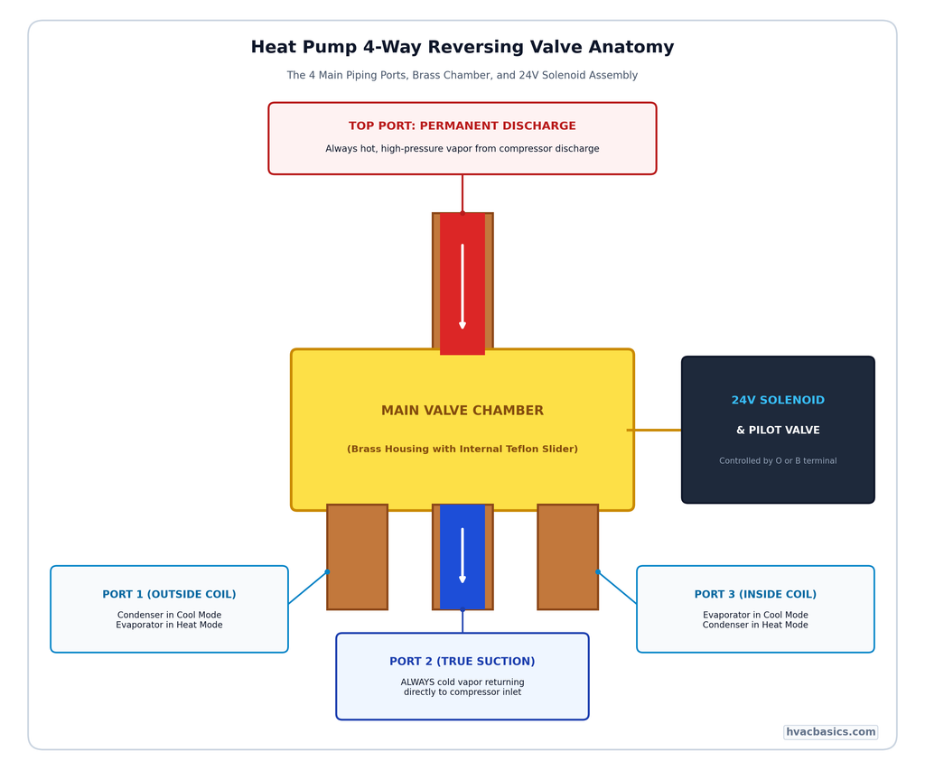
To the untrained eye, the reversing valve looks like a confusing cluster of copper. However, if you follow the “Golden Pipe Rule,” the layout becomes clear:

  • Top Single Pipe: This is the permanent discharge line. It always receives high pressure, high temperature gas from the compressor.
  • Bottom Center Pipe: This is the permanent true suction line. It always leads back to the compressor’s suction side (or accumulator).
  • Bottom Outer Pipes: These connections go to the inside coil and the outside coil. Their roles change depending on the position of the internal slider.

Inside the brass body sits a Teflon slide mechanism. This slider is not moved directly by the magnetic pull of the 24V pilot solenoid. Instead, the solenoid opens a small pilot port that creates a pressure imbalance. It is this differential pressure that physically forced the slider from one side to the other.

Section 2: Cooling vs. Heating Mode (And the O vs. B Confusion)

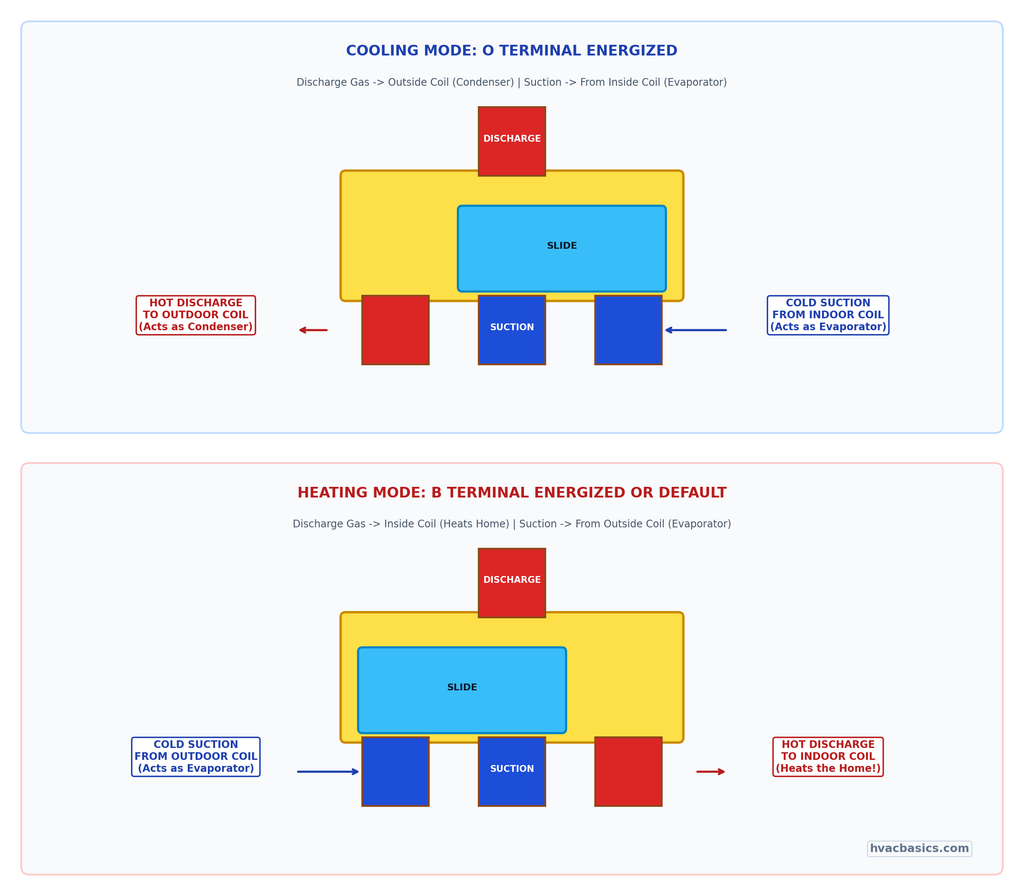
The valve operates by routing the hot discharge gas to one coil while connecting the other coil to the suction line.

  • Cooling Mode: The slider routes discharge gas to the outdoor coil (making it the condenser) and connects the indoor coil to the suction line (making it the evaporator).
  • Heating Mode: The slider moves to route discharge gas to the indoor coil (making it the condenser) and connects the outdoor coil to the suction line (making it the evaporator).

A major point of confusion in the field is the thermostat terminal designation:

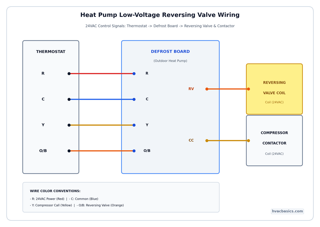
  • O Terminal: This energizes the valve in cooling mode. This is the standard for brands like Carrier, Trane, Lennox, and Goodman.
  • B Terminal: This energizes the valve in heating mode. This is the standard for Rheem and Ruud units.

Common thermostat misconfigurations (setting a Rheem unit to “O” or a Trane unit to “B”) will result in the system heating when it should be cooling, or vice versa. Always check the brand before programming the thermostat.

Section 3: Step-by-Step Troubleshooting

Before you determine a valve is “stuck” and needs replacement, follow this three-step diagnostic workflow:

Step 1: Electrical Verification

Check for 24VAC at the solenoid coil. If voltage is present, check the coil resistance (it should typically be between 15 to 30 ohms). You can also perform a “magnetic screwdriver test” by placing a small screwdriver near the energized coil; if the solenoid is working, you will feel a magnetic pull.

Step 2: The Mechanical Rap Test

If the electrical components are working but the valve won’t shift, the internal slider might be physically stuck. Sometimes, a gentle tap on the valve body with a rubber mallet or the plastic handle of a screwdriver can free a stuck slider. (Never use a metal hammer, as this can dent the brass and permanently ruin the valve).

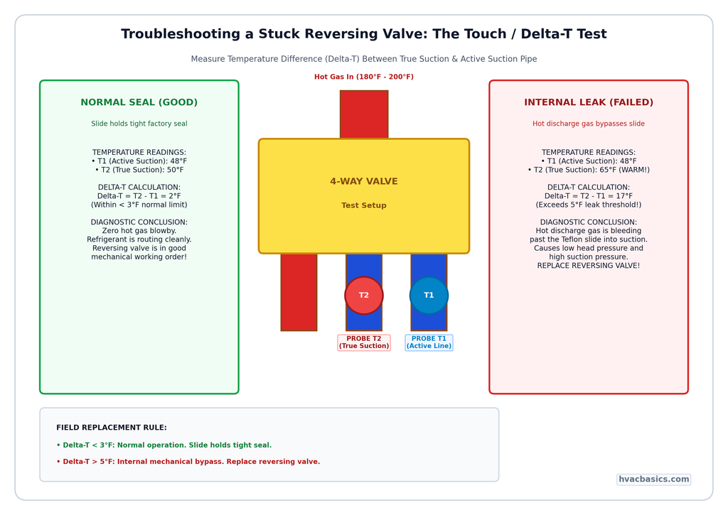
Step 3: The Delta-T Temperature Check

If you suspect the valve is leaking internally (bypassing discharge gas into the suction line), use a pipe clamp thermometer to check the temperature of the true suction line and the line coming from the evaporator coil.

  • Good Valve: A Delta-T of less than 3 degrees F is normal.
  • Leaking Valve: A Delta-T of greater than 5 degrees F proves that high-temperature gas is leaking across the slider into the suction side.
Diagnostic TestHealthy ReadingFailing Reading
Solenoid Voltage24VAC0VAC / Low Voltage
Coil Resistance15 to 30 OhmsOpen (OL) or 0 Ohms
Magnetic TestScrewdriver pulls toward coilNo magnetic pull felt
Delta-T (Bypass)Less than 3 deg FGreater than 5 deg F

Section 4: Replacement Best Practices

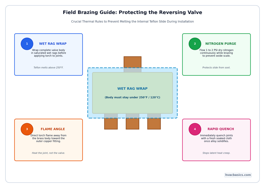
If the valve is truly defective, replacement is a high-stakes task. The internal Teflon slide is extremely sensitive to heat. To ensure a successful install:

  1. Wet Ragging: Wrap the valve body completely in wet rags to keep the internal components cool while brazing.
  2. Nitrogen Purge: Always use a low-flow nitrogen purge to prevent oxidation and scale from forming inside the lines.
  3. Temperature Control: Use a Heat Sink paste or constant water application to ensure the valve body temperature never exceeds 250 degrees F.

Summary and Key Takeaways

  • The top pipe is always discharge; the bottom center is always true suction.
  • Most brands use “O” (energized in cooling), but Rheem/Ruud uses “B” (energized in heating).
  • Always check 24V power and coil resistance before blaming the mechanical valve.
  • A Delta-T higher than 5 degrees F across the suction lines confirms an internal leak.
  • Protect the Teflon slide during brazing by keeping the valve body under 250 degrees F.
Superheat vs. Subcooling: What the Numbers Tell You

Superheat vs. Subcooling: What the Numbers Tell You

Mastering the Vitals of the Refrigeration Cycle

If you want to know what is actually happening inside a refrigeration system, you have to look past the pressures. Gauges are a great start, but they only tell half the story. To truly diagnose a system, you need to understand the relationship between temperature and pressure. Superheat and subcooling are the vital signs of any HVAC unit. Whether you are dealing with a residential split system or a commercial chiller, these two numbers will tell you if the system is healthy, starving, or drowning.

Section 1: Superheat Explained (The Low-Side Compressor Guardian)

Superheat is the thermal insurance policy for your compressor. By definition, superheat is the amount of heat added to a refrigerant vapor after it has undergone a complete phase change from a liquid to a gas. In the evaporator, refrigerant absorbs heat: first as latent heat (changing phase without changing temperature) and then as sensible heat (increasing in temperature).

The Formula

Superheat = Suction Line Temperature (SLT) – Saturated Suction Temperature (SST)

Step-by-Step Measurement Procedure

  1. Attach your manifold gauges to the suction service valve to find the low-side pressure.
  2. Use a P-T chart (or your digital manifold) to convert that pressure into the Saturated Suction Temperature (SST).
  3. Using a calibrated pipe clamp or thermocouple, measure the actual temperature of the suction line near the service valve.
  4. Subtract the SST from the Suction Line Temperature.

Why It Matters: Liquid Slugging vs. Motor Overheating

Superheat ensures that only vapor enters the compressor. If superheat is too low (near 0), you risk liquid slugging, which can destroy compressor valves and bearings. If superheat is too high, the refrigerant vapor is too thin and hot to cool the compressor motor, leading to internal overheating and premature failure.

Fixed Orifice vs. TXV Targets

Targets vary based on the metering device:

  • Fixed Orifice: Superheat is variable and must be calculated using a target superheat chart based on indoor wet-bulb and outdoor dry-bulb temperatures.
  • TXV (Thermostatic Expansion Valve): The TXV is designed to maintain a constant superheat, typically between 8 to 12 degrees Fahrenheit.

Section 2: Subcooling Explained (The High-Side Liquid Prover)

While superheat protects the compressor, subcooling ensures the metering device has a solid column of liquid to work with. Subcooling is the heat removed from a refrigerant after it has completely condensed into a liquid. It represents the sensible heat reduction below the saturation temperature.

The Formula

Subcooling = Saturated Condensing Temperature (SCT) – Liquid Line Temperature

Step-by-Step Measurement Procedure

  1. Attach your manifold gauges to the liquid service valve to find the high-side pressure.
  2. Convert that pressure into the Saturated Condensing Temperature (SCT).
  3. Measure the actual temperature of the liquid line using a thermocouple at the exit of the condenser.
  4. Subtract the Liquid Line Temperature from the SCT.

Why It Matters: Eliminating Flash Gas and Proving Total Charge

Subcooling is the primary indicator of the refrigerant charge level in a TXV-controlled system. High subcooling ensures that the refrigerant does not “flash” back into a gas before reaching the TXV. Without a solid liquid column, the metering device cannot feed the evaporator efficiently.

Rating Plate Targets

Always refer to the manufacturer rating plate on the outdoor unit for the required subcooling. Most modern high-efficiency systems call for a subcooling target between 8 to 15 degrees Fahrenheit.

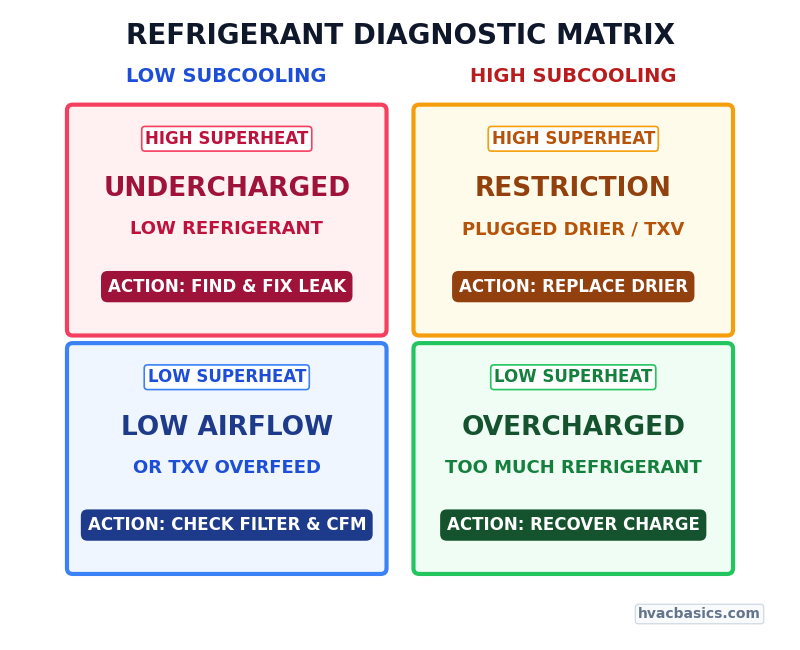
Section 3: The 4-Quadrant Diagnostic Matrix (Reading the Numbers as a Pair)

Diagnosing a system with only one measurement is like trying to find a coordinate with only one axis. You must look at superheat and subcooling together to see the full picture.

1. High Superheat + Low Subcooling (Undercharge)

The system is starving. There is not enough refrigerant to fill the condenser (low subcooling) and the evaporator is running out of liquid halfway through, leading to high sensible heat gain (high superheat).

2. Low Superheat + High Subcooling (Overcharge)

The system is backed up. The condenser is overfilled with liquid (high subcooling), and the evaporator is being flooded, sending liquid or very cold vapor back toward the compressor (low superheat).

3. High Superheat + High Subcooling (Liquid Line Restriction / TXV Restricted)

Refrigerant is getting “stacked” in the condenser because it cannot get through a restriction (like a clogged filter drier or a closed TXV). This leads to high subcooling in the condenser and a starving evaporator with high superheat.

4. Low Superheat + Low Subcooling (TXV Overfeeding / Low Airflow Load)

The refrigerant is moving too fast or there is not enough heat to boil it off. This usually indicates a TXV that is stuck open or an evaporator that is not absorbing heat due to severely low airflow or a dirty coil.

Diagnostic Summary Table

ScenarioSuperheatSubcoolingLikely Fault
UnderchargeHighLowLow refrigerant levels
OverchargeLowHighExcess refrigerant levels
RestrictionHighHighClogged drier or restricted TXV
Overfeeding/Low LoadLowLowTXV stuck open or low airflow

Section 4: Practical Field Rules Before You Touch Your Gauges

Before you start adding or recovering refrigerant based on these numbers, you must ensure the system is ready for testing.

  • Airflow and static pressure first: Never trust your refrigeration numbers if you have a dirty filter, a slipping belt, or a fouled evaporator coil. Airflow issues can mimic refrigeration problems.
  • Insulating temperature probes: Ensure your thermocouples are making good contact with the copper and are insulated from the surrounding ambient air to get an accurate line temperature.
  • Allowing steady-state runtime: A system needs to run for at least 10 to 15 minutes before pressures and temperatures stabilize enough for a valid reading.
  • Matching the charging method: Remember to charge by subcooling for TXV systems and by superheat for fixed orifice systems.

Summary and Key Takeaways

  • Superheat protects the compressor from liquid slugging and ensures proper motor cooling.
  • Subcooling ensures a solid column of liquid reaches the metering device.
  • Always check airflow and static pressure before making charge adjustments.
  • Use the 4-quadrant matrix to differentiate between an undercharge and a restriction.
  • Target subcooling is found on the rating plate; target superheat for fixed orifices is found on a charging chart.
Definitions

Definitions

This is a glossary of terms used across the lessons. Check a term here when it comes up in a lesson, then go back to the lesson and keep working through it.

Air

  • Combustion air: Air required to complete combustion (primary air and secondary air)
  • Ambient air: This is the air that surrounds us
  • Dilution air: The ambient air admitted to the draft hood, draft diverter, or draft regulator. It’s used to cool the venting system and vent the flue gases
  • Excess air: The portion of the combustion air supplied to ensure complete combustion can happen. This is added to combustion air
  • Primary air: The portion of air added to the air/gas mixture prior to ignition
  • Secondary air: The portion of air supplied prior to ignition around the flame

Aldehydes
Aldehydes are a product of incomplete combustion. They’re irritating to the eyes, throat, and nose and smell terrible. Tastes somewhat metallic and are likely accompanied by carbon monoxide

Ambient
The ambient air temperature is the dry-bulb temperature of the surrounding air

Applied voltage
The voltage supplied or applied to the electrical circuit
(also known as supply voltage)

At rest
The appliance main circuit disconnect is in the open position not allowing the circuit to be energized. This could be the door switch in a furnace. Any heating or cooling thermostats connected to the circuit would be sitting in a non-operating position.

BTU
British Thermal Unit is the measurement used to measure heat. It takes 1 BTU to raise the temperature of 1LB of water 1°F

BTUh
British Thermal Units per hour

Calorific value
The calorific value (also known as heat content) of a fuel is the amount of energy released when a volume of fuel is burned expressed in BTU per cubic foot of natural gas or propane
(also known as: heat content)

Capacitor start/capacitor run
Has a start capacitor in series with the secondary (aka start or auxiliary) winding for high starting torque. It also has a run capacitor that is in series with the secondary (aka start or auxiliary) winding after the start capacitor is taken out of the circuit

Capacitor start/induction run
Similar to the capacitor start/capacitor run motors. Uses a start capacitor for the secondary (aka start or auxiliary) winding for high starting torque. A potential relay removes the capacitor from the circuit at about 3/4 of the startup speed. No run capacitor is used.

Carbon monoxide
A byproduct of incomplete combustion. A colorless, odorless, and tasteless gas with a relative density of 0.96

Closed switch
The position a switch must be in to allow electricity to flow

COAF
CO air-free. Flue gas CO readings are inaccurate since the added excess air dilutes them. The COAF measurement compensates for the excess air and is used to express CO levels in the flue gas reading

Conductor
Materials that allow electricity to flow. Copper, aluminum, silver, gold are some examples of conductors. Wiring in your house would be a conductor wrapped with an insulator

Current
The flow of electrons through a conductor. Measured in amperes (amps)

Dew-point
Dew-point is the temperature that air must be cooled to in order for water vapor to condense (at which the air is 100% moisture). The closer the dew-point is to the actual temperature, the more moisture in the air.

Dirt pocket
Used in a piping system to collect dirt.

Drip pocket
Used in a piping system to collect condensate.

Dry-bulb
Dry-bulb temperature is the temperature of the air around you measuring only the sensible heat and is not affected by the moisture in the air. This would be the temperature you measure when using a normal thermometer.

Flame impingement
Flame touching metal surface inside heat exchanger or cold air blowing around the flame and cooling it below ignition temperature.

Flue gas
Appliance exhaust removed through exhaust venting or chimney.
(also known as exhaust)

Ignition control board
Common in older systems. They control the gas valve, igniter, flame sensor, and the damper (when used). This is like a step-down from a full furnace control board.

Ignition temperature
Temperature the air:gas mixture will support combustion. Between 1200°F and 1300°F for natural gas and 920°F for propane.

Inshot burner
Used in most modern furnaces. A combustion blower is used to pull the flames through the burner tubes into the heat exchanger.

Insulators
An insulator does not allow an easy flow of electricity. Glass, plastic, etc. An insulator can also be called a non-conductor.
(also known as non-conductor)

Integrated Furnace Control
Integrated Furnace Control is also called the IFC or the control board. The IFC controls everything an ignition control board would and more. All safety controls, combustion blower, flame proving, gas valve, and the blower are all controlled by the IFC.
(also known as: control board, IFC)

Isolation relay
Normally a SPST (single pole single throw) relay. Used to separate two different voltages in a system.

LMR
Longest Measured Run. It’s the distance from the supply (meter or regulator) to the furthest appliance to be connected. Used in pipe sizing.

Load
(With regard to electrical) a good load in a circuit does useful work. This could be as simple as turning on a light

(With regard to gas piping) The appliance input in BTUh. This can be found on the appliance rating plate

LRA
The amperage a motor will draw when the supply voltage is applied, and the rotor is locked (not turning). This lasts for a second or less before the motor gets up to speed.
(also known as lock rotor amperage)

Mercaptan
Added smell to natural gas to make it easier to detect since by default natural gas is both odorless and colorless. Without this smell, gas leaks wouldn’t be detected in most cases until it’s too late

Metric
Unit of measurement based on meter, cm, kg, etc

Ohm’s Law
The current flowing in a circuit is directly proportional to the applied voltage. As current increases, resistance decreases. If resistance increases, current decreases.

Overfired
Gas valve pressure adjusted higher than the data-plate requires.

Perfect combustion
Combustion that provides the exact fuel to air ratio and extracts all energy from the fuel at 100% efficiency. Perfect combustion does not exist in the real world.
(also known as stoichiometric combustion)

Piezoelectric
A popular pilot starter. They have the ability to generate a high voltage to supply a spark when a mechanical force is applied. Popular with BBQ starters.

Pilot

  • Continuous pilot: AKA standing pilot. Burns the entire time without turndown regardless if main burner fires or not
  • Expanding pilot: Burns at low turndown throughout the entire time the burner is in service, except when a call for heat. Upon a call for heat, the pilot is increased to expand the flame to ignite the main burner
  • Intermittent pilot: Activated each call for heat and the pilot stays active until the main burner powers off
  • Interrupted pilot: Activated each call for heat, but the pilot does not function after the main burner powers on

Plenum
Supply Plenum
Sheet metal box connected directly to the supply outlet of the HVAC appliance that directs the heated or cooled air to the ductwork.

Return Plenum
Most units have multiple, or at least one return duct(s) in the house moving conditioned room air to the HVAC unit. When air is forced through the supply ductwork, conditioned room air gets pulled throughout the structures return ductwork into the central return air plenum to be moved through the HVAC appliance to be heated or cooled.

Polarity
Polarity is the direction of current flow in a circuit from the two poles, positive and negative

In an AC circuit, each pole alternates between positive and negative 60 times per second

In a DC circuit, it’s between the negative and positive with current flowing from negative to positive

PSC
Permanent Split Capacitor motors have a run capacitor permanently connected in series with the start winding. That makes the start winding the auxiliary winding once the motor reaches running speed.

Relative density
The comparison between the weight of a volume of a liquid or vapor and the weight of an equal volume of air or water.
(also known as specific density)

Relative humidity
Relative humidity is the amount of water vapor in the air, expressed as a percentage, compared to the amount of water vapor it could hold at that temperature if fully saturated.

Series circuit
A series circuit provides only one path for current to flow.

Transformer

  • Step up transformer: A transformer with a higher voltage at the secondary winding terminals than at the primary winding terminals. The secondary coil has a greater amount of windings
  • Step down transformer: A transformer with a lower voltage at the secondary winding terminals than at the primary winding terminals. The secondary coil has a fewer amount of windings. Normally line voltage (120v) to control voltage (24v)

Venturi
When gas passes through a passage that has a reduction in size this causes an increase in speed to make the pass-through possible to happen and draws air in with it. Paint spray guns use the venturi effect to pass paint through the gun

Related posts

Non-invasive testing

Non-invasive testing

Take any chance you have to skip connecting refrigerant gauges to a system. Each time you attach your gauges, you remove a small amount of refrigerant from the system through your hoses. The longer the hoses, the more charge that’s lost. After a few times of doing this, you might end up chasing a leak that doesn’t even exist.

Using ball valve hoses you can get most of the refrigerant back into the low side of the system before disconnecting, but if you don’t need to connect in the first place, don’t. Smart probes are another option to minimize release.

Connecting gauges can also cause schrader cores to stick and release the refrigerant. The technician can contaminate a system if connecting hoses incorrectly. It’s best to avoid all these risks when you can.

I’m not saying it’s never a good idea to connect gauges to a system. On maintenances or a service call for an electrical issue there really almost never is a need to connect.

Superheat Without Gauges

Step 1: Getting the required superheat

Firstly we need to calculate what our superheat should be. You can use the superheat charging chart from the system, the Emerson Check and Charge app, or a table like the one above. Whichever you use, you will need the indoor wet bulb measured in the return air and the outdoor dry bulb measured in the shade by the condenser.

The return air wet-bulb for this system is 64.5°F, rounded to 64°F, and the outdoor temperature is 70°F at the condenser in the shade.

This example system has a required target superheat of 21°F.

Step 2: Subtract evaporator design temperature difference from the indoor dry bulb

Next, we need to get the return air dry bulb. The return air dry-bulb temperature here is 75°F.

We subtract the evaporator design temperature difference from the return air dry bulb. For most residential and lite commercial cooling equipment, we use 35°F.

75°F – 35°F = 40°F

Evaporator design temperature difference is the difference in the evaporator saturation point (which you see on the low side of your refrigeration gauges) and the return air temperature. Essentially, subtracting the evaporator design temperature difference gives you the saturation temperature (which is your temperature you would read on your refrigerant gauges) of the low side of the system. 40°F from this example converts to 68.5 psig using the pressure-temperature relationship. This is an R22 unit.

Step 3: Calculate

Now to bring it all home we take the evaporator saturation temperature from step 2 and add the required superheat from step 1.

40°F + 21°F = 61°F

Remember the 40°F is what we would see on our gauges had you hooked them up. We got this number without ever having to do that.

Step 4: Confirm proper superheat

Take the suction line outlet temperature as close to the evaporator as you can for the most accurate temperature. This coil has an outlet temperature of 61.2°F.

A system charged by superheat is considered correctly charged when within +/- 5°F.

Subcool Without Gauges

Step 1: Get condenser discharge air temperature

The condenser discharge air temperature will give the saturation temperature value of the refrigerant in the condenser. The saturation temperature can be converted to the refrigerant gauge pressure if needed using the pressure-temperature relationship by using a refrigerant slider.

Take the condenser discharge air temperature across a few areas of the outlet of the condenser. Generally, the highest number recorded after a few attempts is what’s used.

This system has a condenser discharge air temperature of 95°F.

Step 2: Liquid line temperature

Make sure to cover the temperature probe to protect from direct sunlight causing false readings. Record the liquid line temperature about 6” or so from the liquid line service valve.

This system has a liquid line temperature of 78°F.

Step 4: Calculate subcooling

The formula for calculating subcool is condenser saturation temperature – liquid line temperature

95°F – 78°F = 17°F subcooling (required subcooling of 16°F)

A system charged by subcooling is considered correctly charged when within +/- 1°F.

As mentioned earlier, the 95°F from step 1 can be converted to the refrigerant gauge pressure using a refrigerant slider or refrigerant slider app. 95°F for a 410A system converts to 299 psig using the pressure-temperature relationship.

95°F for a 410A system converts to 299 psig.
Plenum

Plenum

Supply Air

Sheet metal box connected directly to the supply outlet of the HVAC appliance that directs the heated or cooled air to the ductwork.

Return Air

Most units have multiple, or at least one return duct in the house moving conditioned room air to the HVAC unit. When air is forced through the supply ductwork, conditioned room air gets pulled throughout the structures return ductwork into the central return air plenum to be moved through the appliance to be heated or cooled.

TH, TR and TH/TR

TH, TR and TH/TR

You’ll run into these terminals commonly on older standing pilot furnaces. TH/TR is a common connection, but that doesn’t explain much in itself.

We’ll overview which each of these terminals is intended for:

TH – The 24v hot leg from the thermostat on a call for heat (R+W closing on the thermostat) to the gas valve (TH terminal) to open the solenoid to allow gas to flow, assuming the transformer is working and the high limit is closed (allowing for the flow of electricity)

TR – The 24v common/return side of the transformer.

TH/TR – Is not internally wired to the gas valve. Not using this makes no difference to the circuit. You could run your 24v hot from the transformer directly to your NC (normally closed) high limit in the above example and be fine. TH/TR is nothing more than a convenience terminal. Joining these wires with a marette (wire nut or terminal multiplier) does the same thing as this terminal

Tankless water heater

Tankless water heater

The following sequence is for the Rinnai tankless water heater. If you can learn this sequence, you will have a good understanding across the board for all brands out there as they all follow a similar sequence of operation.

Step 1. Upon a call for hot water, the water flow sensor will sense water flow and send a pulsing signal to the PCB (control board). The gallons per minute minimum to start the unit start trial for ignition will differ across models and brands, but 0.4 gpm is common

Step 2. The combustion fan starts. The positive pressure created at the outlet of the combustion fan to force out the exhaust in-turn creates a negative pressure at the inlet of the combustion fan which draws air in for combustion.

To simplify what is said in step 2 a bit further:

  1. As the fan is turning, it’s pushing air through the heat exchanger and out the exhaust
  2. Air moves through the heat exchanger for the combustion process and out of the exhaust venting
  3. As the fan is pushing air out (positive pressure exhaust side) the fan is pulling in the air at the same time (negative pressure combustion airside)

Step 3. The sparker starts, the gas valve opens to low fire, flame rod proves flame, and then the sparker stops.

Step 1, 2, and 3 happens almost instantly from the time the user turns on a hot water faucet to the flame sensing. However, it can take some time to move the hot water from the tankless unit to the user depending on the distance.

Step 4. The PCB (control board) is continually watching and adjusting the fan speed, water flow rate, outlet water temperature, user water temperature setpoint, and flame signal.

As the user has the demand for water, the fan speed will adjust along with the modulating gas valve input to meet the demand for heating water. There’d be no point in firing all gas valve solenoids (SV 1/2/3/4) and monitoring with both flame rods (FR1/2) for a small request for hot water when just SV1/SV2 and FR1 would meet the hot water request.

Water is heated above setpoint and tempered down using the bypass. The water leaving the water heater is monitored by the outgoing water temperature thermistors at all times to make sure it’s about +/- 1 or 2°F of the unit setpoint. Heating higher and tempering down allows for a higher flow rate.

Example: User has the setpoint of the water heater to 120°F. Actual water is heated to 140°F and tempered down to 121°F measured on the outlet of the tankless water heater using the outgoing water temperature thermistor.

Step 5. Once flow rate drops to about 0.26gpm, the shutdown process begins. The gas control valve closes. The water flow control valve switches to a standby position. The combustion fan continues to run for a little bit to make sure the combustion chamber is free of fumes.

The PCB (control board) watches all components while the unit sits waiting for the next call for heat, so it’s essential not to remove power from these units when going away for an extended time especially in freezing conditions. These units are usually equipt with freeze protection and removing power causes freeze protection to be disabled.

90%+ Furnace

90%+ Furnace

The following is an example of a 90%+ furnace. Things may differ slightly from manufacturer to manufacturer, but they’ll all be pretty close, and theory will remain the same.

  • Furnaces equipped with a control board are continually checking to confirm rollout switches and the high-limit switch are all closed. It also sends 80V – 110V to the flame sensor to prove there’s no flame present before ignition as well with no call for heat
  • The thermostat has a call for heat and closes R+W switch
  • The control board completes a safety check to ensure rollouts and high-limit are closed (completed circuit). If a high-limit or flame rollout is open, or a pressure switch is closed before running the combustion blower, the control board will display an error and run the blower to get the attention of the homeowner
  • Combustion blower starts up to ensure exhaust venting, primary heat exchanger, secondary heat exchanger, combustion air, and drain lines are clear. The contacts of the pressure switch will close (to complete the safety circuit) if no blockages exist. If the combustion blower cannot close the contacts of the pressure switch, an error will be displayed. The combustion blower will try a couple more times before going into a lockout
  • The igniter will start to warm up for around 10 – 20 seconds
  • The trial for ignition begins. The gas needs to ignite the burners and flame sensor sense the flame. The gas valve will energize for about 7 seconds and ignite the burners
  • The flame will be proven using flame rectification. If the flame is not proven within a few seconds, the gas valve de-energizes and the process starts again. The furnace usually tries three times before going into lockout and displaying an error
  • Assuming flame is proven, the blower will begin after the heat exchanger has had time to warm up. Waiting for the heat exchanger to warm up helps not to blow cold air on the homeowner. There’s usually a delay of 30 seconds or so
  • Once the thermostat is satisfied, the gas valve stops the flow of gas, and the blower will continue to run for about 90 seconds to cool off the heat exchanger and use the rest of the heat from the heat exchanger
  • The combustion blower runs for a short time as well to endure the exhaust is cleared
Thermostat

Thermostat

The thermostat is the command center for an HVAC system. The thermostat is what will switch the equipment on and off. Most people are familiar with the thermostat on the wall for their heating and cooling, but they’re in almost everything from water heaters to freezers and kitchen equipment.

Modern thermostats sense temperature using a thermistor. The thermistors resistance value changes depending on the surrounding temperature. A small microcontroller converts the measured resistance to temperature and decides based on desired settings if heating or cooling should be switched on.

Modern thermostats have the benefit of being programmable.

Visual of electrical flow

How the C Wire Works

The C wire is also known as the common wire. The C wire runs from your heating or cooling unit 24v common to the thermostat. The C wire connection most often used are the designated wire connections from the furnace to the thermostat on the control board at the furnace or air handler. On older units without a control board, the common side of the transformer is used.

Most Wi-Fi thermostats require a common wire to provide constant power to the thermostat. Thermostats without a C wire will only have a complete circuit during a call for heating or cooling. An example of this being R+W closing to heat a space. Without a complete circuit, a thermostat needs to rely solely on batteries to power the display.

C wire powering thermostat in standby

What if I don’t have a common wire?

Generally, a smart thermostat will need five wires:

R – 24v from the furnace or air handler transformer

W – Heating

Y – Cooling

G – Fan

C – common

It’s very common to run into thermostats with only four wires. When you only have R, W, Y, and G you can still make it work. It’s best just to run the new wire, but that’s not always practical or cost-efficient.

Power Stealing

Nest is the most popular smart thermostat that takes advantage of power stealing and does not require a c wire.

These thermostats “steal” power by pulsing a call for heat. The thermostat very quickly creates and ends a call for heat to close the circuit in an attempt to charge the battery inside the thermostat. Most homeowners would never know this is happening, but on older style furnaces, the homeowner might notice the furnace does startup.

Power Extender Kits or Wire Saver Modules

Ecobee includes what they refer to as the PEK (power extender kit) and Honeywell has what they call the wire saver kit. Venstar makes the Add-a-Wire.

Essentially these kits allow a homeowner to run a smart thermostat with only four wires (R, W, Y, G) and the kit will split a signal removing the need for the 5th wire (C wire).

Fan G for C

If you have wires R, W, Y, and G at your thermostat, you can remove G and move it over to C at your thermostat and on your control board at the HVAC unit. The thermostat will now have a constant power source, but the homeowner will lose the ability to turn the fan on manually if they’d like to.

Run New Wire

Running new wire is ultimately the best option, but not always practical given time and material cost to the customer. Some residences can seem almost impossible to run a new wire from the unit to the thermostat, but when this is an option, it’s the best option.

Millivolt furnace with WiFi thermostat

There’s still a lot of millivolt furnaces out there. You’ll find a lot of the owners of them won’t give them up because “they don’t make these furnaces like they used to.” However, many of these owners want the fancy Wi-Fi thermostats. If you’re not sure how to get the 24v out of a millivolt system, this tip is for you.

Let’s go over a couple of basics.

You’ll be using an isolation relay which is just a SPST (Single Pole, Single Throw) NO (normally open) relay to separate the different voltages in a system.

Millivolt furnaces operate using a thermopile to power the system. A thermopile is merely multiple thermocouples. Some millivolt systems will also use a thermocouple for flame safety. Under load, a thermopile should operate at no less than 190mV at the absolute minimum.

Please refer to the wiring diagram while reading the information below.

You’re going to feed 120v to the transformer which is stepped-down to 24v for the thermostat.

Wire your hot side of the 24v transformer to R on the Wi-Fi thermostat.

Connect W on the thermostat to one side of the relay coil. On the other side of the coil, you’ll add C from the thermostat, and common wire of the transformer.

You’re going to take the thermostat wires off your old millivolt thermostat and add them to the NO terminals on the relay.

Upon a call for heat, the relay coil will be powered closing the SPST relay powering the millivolt system (NO terminals) for heat.