
series
noun
- a number of things, events, or people of a similar kind or related coming one after another.
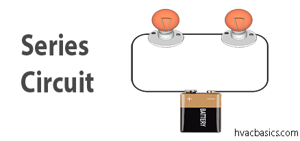
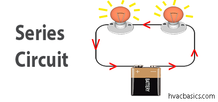
So given the above definition, a series circuit is when there’s only a single path for current to flow. Any break in the wiring or a faulty load will stop current throughout the entire series circuit.
A load is anything in the circuit that does useful work, like the lightbulb in the example below. The inexpensive and/or old Christmas lights have this downfall. When a single bulb burns out, the entire string of lights goes out.
No flow = no go
Rules of a Series Circuit
- Rule 1: Current is the same throughout the circuit
Since current stays the same through the circuit, this makes calculations using Ohm’s Law easier.

Each component in a series circuit has the same current flow.
I total = I 1 = I
- Rule 2: The total resistance of a series circuit is equal to the sum of the individual resistances.

Adding the individual value of each component in a series circuit will give the total resistance of the circuit.
In the above example, we have two values.
R total = R1 + R2
R total = 5 Ω + 5 Ω
R total = 10 Ω
- Rule 3: The total voltage drop in a series circuit is equal to the applied voltage of the circuit.

The total voltage drop across each resistor must add up to the total voltage supplied to the circuit from the battery.
V total = V 1 + V 2
V total = 6 V + 6 V
V total = 12 V
Using Ohm’s Law any of these totals can be found as long as you have at least 2 values.

Voltage
E = I x R
E = 1.2 A x 10 Ω
E = 12 V
Resistance
R = E / I
R = 12 V / 1.2 A
R = 10 Ω
Amperage
I = E / R
I = 12 V / 10 Ω
I = 1.2 A
If at any point there’s a break in the wiring or a load is faulty, no current will flow. No flow = no go.

What this means on a service call
A series circuit gives current one path and no way around a break. That is the point to carry into a service call. If one part in the path opens, current stops in the whole path. The Christmas lights in the original post show it plainly. One bulb burns out, the whole string goes out, even though the other bulbs are still good.
Think of switches and safeties in the same way. A switch, a fuse, or a safety control in series with a load can stop the load when it opens. That does not mean the load failed. It means the path is open somewhere. Find the open part before you replace a load that may still be good. Check each part in the path in turn, and do not assume the first part you test is the fault.
Numbers and measurements you will see
The numbers in this post all come from one example, and they must agree with each other. Use that agreement as a check. If a reading does not fit the three rules, the circuit in front of you is not the example, or a part has changed.
- Current is the same, 1.2A. In the example, 12V divided by 10 ohms gives 1.2A. That same 1.2A flows through each part. A different current at two points in one series path means a reading error, a second path, or a changed circuit.
- Resistance adds, 10 ohms. In the example, 5 ohms plus 5 ohms gives 10 ohms total. Add each part to get the total. The total is higher than any one part.
- Voltage drops add, 12V. In the example, 6V plus 6V gives 12V total. The drops across the parts must add up to the applied voltage. If the drops do not add up, a reading is wrong or a part is missing from the count.
- Ohm’s Law check for voltage. E equals 1.2A times 10 ohms, which equals 12V.
- Ohm’s Law check for resistance. R equals 12V divided by 1.2A, which equals 10 ohms.
- Ohm’s Law check for current. I equals 12V divided by 10 ohms, which equals 1.2A.
A common mistake
The most common mistake is to replace the load when the path is open somewhere else. A load with 0V across it and no current may be good, with an open switch, fuse, or wire upstream. Test for voltage at the load, then test each part in the path, before you condemn the load.
A second mistake is to expect the full applied voltage across each part. In series, voltage is shared. In the example, each resistor drops 6V, not 12V. A 6V reading across one part can be correct. Add the drops together before you call a reading wrong. A third mistake is to measure current at one point and assume it will differ at another point in the same series path. It will not, unless the path has changed.
Check it in the field
- Check the applied voltage at the source, with the circuit powered as the equipment instructions allow. Record it. In the example, that value is 12V.
- Measure the voltage drop across each part in the path, one part at a time. Record each drop. Add the drops together and compare the total with the applied voltage.
- Check current in the path. In a series path, the current should be the same at each test point. Use Ohm’s Law to cross-check the current, resistance, and voltage figures against each other.
- If current is 0A, find the open. With the power off, and the circuit proved dead, check continuity through each part and each wire in the path, one at a time, until you find the break. Repair only the open part, then retest.
Do resistance and continuity checks with the power off. Prove the circuit dead with a voltage test first. Do not touch bare metal while you test a live circuit. Keep hands clear, use insulated leads, and stop and get help if you are unsure about the power state.
Related posts
These posts belong together. Use the summary for the short version, then work through each part on its own.
- Voltage, current, and resistance summary: a short recap of voltage, current, and resistance together.
- Voltage: the push that makes current flow, and how to read a voltage test.
- Current (amps): what flow means, and how to check it without guessing.
- Resistance: what opposition to flow means, and why a load must have resistance.
- Parallel Circuits: more than one path, with total resistance lower than any one branch.
- Ohm’s Law: how voltage, current, and resistance relate, with worked examples.