
A field guide to avoiding premature valve condemnation and mastering the 4-way mechanism.
The reversing valve is the heart of a heat pump’s ability to provide year-round comfort. It is the component responsible for seasonal switching, physically redirecting refrigerant flow to turn an air conditioner into a heater. For many technicians, however, the reversing valve is a source of frustration. It is often misdiagnosed and condemned prematurely when the real issue lies in the electrical system or the refrigerant charge. Understanding exactly how these valves function is the first step toward faster, more accurate service calls.
Section 1: Anatomy of the 4-Way Valve (The Golden Pipe Rule)
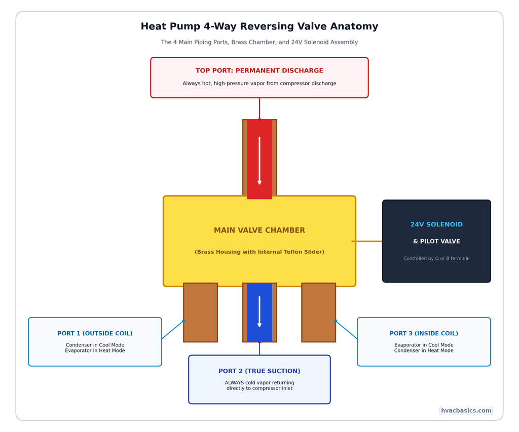
To the untrained eye, the reversing valve looks like a confusing cluster of copper. However, if you follow the “Golden Pipe Rule,” the layout becomes clear:
- Top Single Pipe: This is the permanent discharge line. It always receives high pressure, high temperature gas from the compressor.
- Bottom Center Pipe: This is the permanent true suction line. It always leads back to the compressor’s suction side (or accumulator).
- Bottom Outer Pipes: These connections go to the inside coil and the outside coil. Their roles change depending on the position of the internal slider.
Inside the brass body sits a Teflon slide mechanism. This slider is not moved directly by the magnetic pull of the 24V pilot solenoid. Instead, the solenoid opens a small pilot port that creates a pressure imbalance. It is this differential pressure that physically forced the slider from one side to the other.
Section 2: Cooling vs. Heating Mode (And the O vs. B Confusion)
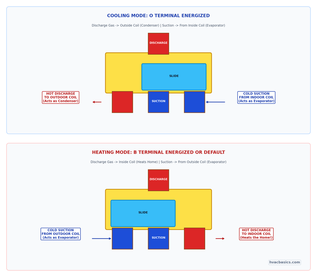
The valve operates by routing the hot discharge gas to one coil while connecting the other coil to the suction line.
- Cooling Mode: The slider routes discharge gas to the outdoor coil (making it the condenser) and connects the indoor coil to the suction line (making it the evaporator).
- Heating Mode: The slider moves to route discharge gas to the indoor coil (making it the condenser) and connects the outdoor coil to the suction line (making it the evaporator).
A major point of confusion in the field is the thermostat terminal designation:
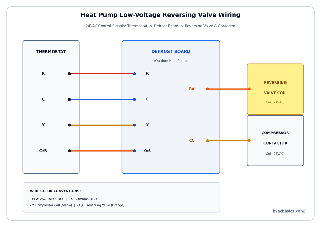
- O Terminal: This energizes the valve in cooling mode. This is the standard for brands like Carrier, Trane, Lennox, and Goodman.
- B Terminal: This energizes the valve in heating mode. This is the standard for Rheem and Ruud units.
Common thermostat misconfigurations (setting a Rheem unit to “O” or a Trane unit to “B”) will result in the system heating when it should be cooling, or vice versa. Always check the brand before programming the thermostat.
Section 3: Step-by-Step Troubleshooting
Before you determine a valve is “stuck” and needs replacement, follow this three-step diagnostic workflow:
Step 1: Electrical Verification
Check for 24VAC at the solenoid coil. If voltage is present, check the coil resistance (it should typically be between 15 to 30 ohms). You can also perform a “magnetic screwdriver test” by placing a small screwdriver near the energized coil; if the solenoid is working, you will feel a magnetic pull.
Step 2: The Mechanical Rap Test
If the electrical components are working but the valve won’t shift, the internal slider might be physically stuck. Sometimes, a gentle tap on the valve body with a rubber mallet or the plastic handle of a screwdriver can free a stuck slider. (Never use a metal hammer, as this can dent the brass and permanently ruin the valve).
Step 3: The Delta-T Temperature Check
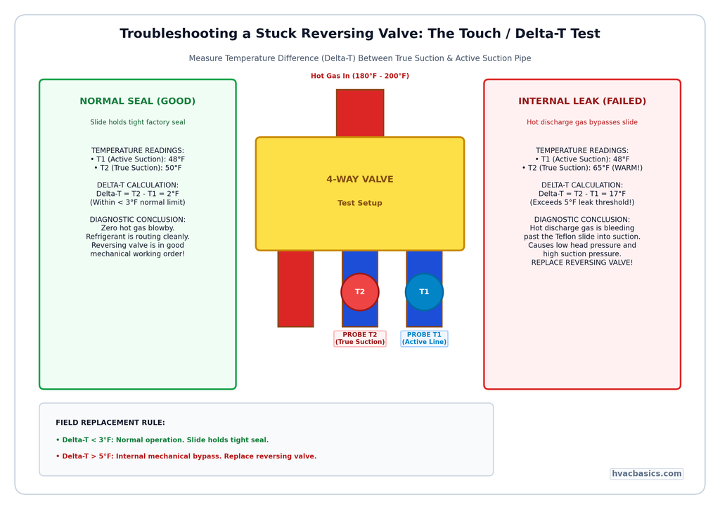
If you suspect the valve is leaking internally (bypassing discharge gas into the suction line), use a pipe clamp thermometer to check the temperature of the true suction line and the line coming from the evaporator coil.
- Good Valve: A Delta-T of less than 3 degrees F is normal.
- Leaking Valve: A Delta-T of greater than 5 degrees F proves that high-temperature gas is leaking across the slider into the suction side.
| Diagnostic Test | Healthy Reading | Failing Reading |
|---|---|---|
| Solenoid Voltage | 24VAC | 0VAC / Low Voltage |
| Coil Resistance | 15 to 30 Ohms | Open (OL) or 0 Ohms |
| Magnetic Test | Screwdriver pulls toward coil | No magnetic pull felt |
| Delta-T (Bypass) | Less than 3 deg F | Greater than 5 deg F |
Section 4: Replacement Best Practices
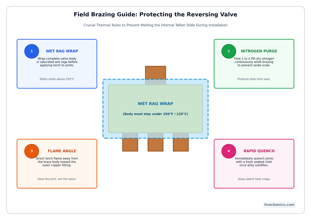
If the valve is truly defective, replacement is a high-stakes task. The internal Teflon slide is extremely sensitive to heat. To ensure a successful install:
- Wet Ragging: Wrap the valve body completely in wet rags to keep the internal components cool while brazing.
- Nitrogen Purge: Always use a low-flow nitrogen purge to prevent oxidation and scale from forming inside the lines.
- Temperature Control: Use a Heat Sink paste or constant water application to ensure the valve body temperature never exceeds 250 degrees F.
Summary and Key Takeaways
- The top pipe is always discharge; the bottom center is always true suction.
- Most brands use “O” (energized in cooling), but Rheem/Ruud uses “B” (energized in heating).
- Always check 24V power and coil resistance before blaming the mechanical valve.
- A Delta-T higher than 5 degrees F across the suction lines confirms an internal leak.
- Protect the Teflon slide during brazing by keeping the valve body under 250 degrees F.