
Master HVAC/R Theory Through Clear, Full-Scale Technical Diagrams
Trade school textbooks bury simple mechanical principles under dense formulas. HVAC Basics gives apprentices, students, and technicians direct, step-by-step visual breakdowns that mirror what you actually see and troubleshoot in the field.
- High-Resolution Schematics: Built to be readable on phones, tablets, and desktop screens.
- Direct Field Applications: Connecting scientific theory to real-world diagnostic calls.
- Technician-Verified: Focusing on mechanical safety, proper measurements, and system protection.
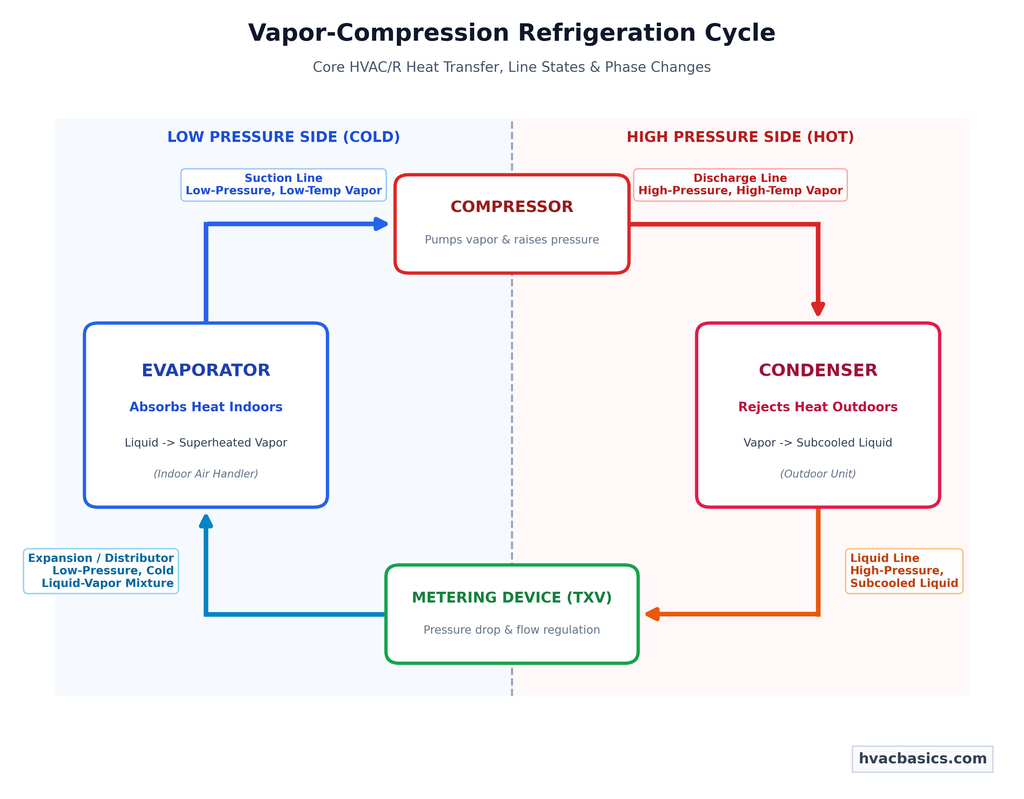
Understanding the 4 Core Components & Phase Changes
Every air conditioning and heat pump system relies on the same core physics: absorbing heat from an indoor space and rejecting it outside.
Key Concepts Explained in this Guide:
- The High Side vs. Low Side: How the compressor and metering device (TXV) divide the system into high-pressure and low-pressure zones.
- Phase Changes in the Coils: Why latent heat transfer (boiling and condensing) moves far more heat than sensible temperature changes alone.
- Diagnostic Proving Points: Why measuring superheat verifies evaporator performance and subcooling verifies condenser charge.
8-Stage Heating Ignition & Safety Interlock Workflow
When a furnace locks out, guessing wastes time and risks equipment damage. Follow the electrical and pneumatic sequence to pinpoint exact failure points.
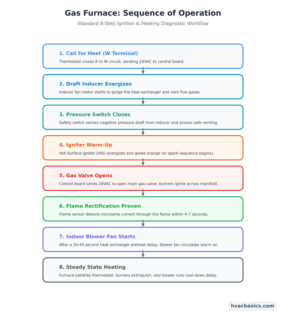
Step-by-Step Diagnostic Checklist:
- Call for Heat (W): Confirm 24VAC between W and C on the control board.
- Draft Inducer: Check voltage to inducer motor; verify wheel spins freely.
- Pressure Switch: Measure switch contact closure with a manometer and voltmeter to prove draft.
- Igniter: Check resistance (ohms) across the hot surface igniter element with system off and voltage to ignitor with system running.
- Gas Valve & Burners: Verify 24VAC to gas valve solenoid and observe manifold ignition.
- Flame Rectification: Measure DC microamps (uA) through the flame sensor rod to ground.
- Indoor Blower: Ensure blower relay engages after factory heat delay to prevent high-limit tripping.
HVAC Basics bridges the gap between dense technical manuals and hands-on field troubleshooting. Every guide is written with safety, practical diagnostic order, and clear visual schematics at the forefront.